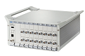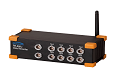

SE-864U Static Stress-strain Testing and Analysis System is an intelligent data acquisition system. Each instrument has 36 channels, wireless and wired communication. It can be controlled by computer software or mobile APP. It is suitable for model and other tests with relatively concentrated measuring points. The measurement of physical quantities such as strain stress, force and displacement is realized. The system can be widely used in the static structural performance test of universities, industrial research institutes, engineering testing sites and product development process.
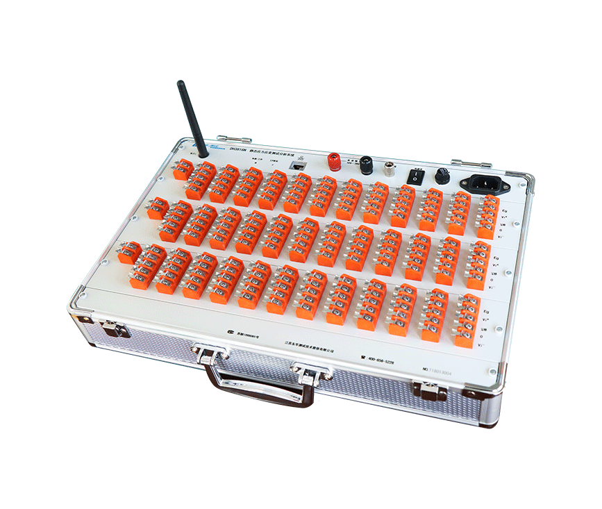
It adopts high strength aluminum alloy case, light and strong. Reasonable structure, high stability, convenient disassembly and maintenance.
Through Ethernet or wireless WiFi communication with the computer, and through Ethernet module expansion, can achieve more than 1024 expansion.
Multi bridge mode switching: support full bridge, half bridge, 1 / 4 bridge (three wire system self compensation), 1 / 4 bridge (public compensation) state, easy to use and easy to operate.
With various bridge sensors, it can accurately test the force, pressure, displacement and other physical quantities.
Cables resistance automatic correction function: through the control software, the cable resistance measurement and automatic correction can be completed with one key, so as to improve the test accuracy.
Bridge circuit self-test function: combined with software, it can accurately judge the short circuit, open circuit and other faults of bridge circuit.
Any measurement point can be set as the compensation measuring point, or the common compensation terminal can be used for compensation.
According to the output sensitivity of the sensor, the unit dimension of the measured physical quantity is normalized and displayed directly.
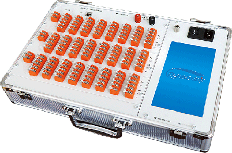
The use of inclined plug-in high temperature terminal is convenient for wiring, and soldering iron can be used repeatedly, and the terminal will not be deformed.
DC power supply is supported.
| Number of Input Channel | 12 channels + 1 channel common compensation per card, 3 card slots per chassis |
| Full-scale Voltage Value | ±60mV, 0 ~ 2V switching |
| Strain Measurement | |
| Full-scale Strain Value | ±60000με |
| Min. Resolution | 0.1με |
| Indication error | ≤0.5%±3με |
| Noise | ≤0.5μεRMS |
| Zero Drift | ≤3με/4h |
| Self-Balancing Range | ±30000με (±2% of strain gauge resistance) |
Strain Gauge Sensitivity Coefficient | 1.0 ~ 3.0 (Auto. calibrating) |
| Bridge Excitation | |
| Bridge Configuration | Full, half, three-wire quarter bridge, public compensation quarter bridge |
| Bridge Completion Resistors | 120Ω, 350Ω (Three-wire quarter bridge) 60Ω ~ 20000Ω (Half bridge / Full bridge) |
| Bridge Voltage | 2V, 5V, 10V DC |
| Output voltage range (DC) | 2V |
| Accuracy | ≤0.1% |
| Stability | ≤0.5% per hour. |
| Maximum output current | 30mA per channel. |
| Resistance correction range | 0~100Ω |
| Communication | Gigabit Ethernet / WiFi |
| A/D Converter | 24 bits |
| Sampling Rate | 1Hz, 2Hz, 5Hz, 10Hz, 20Hz, 50Hz, 100Hz, 200Hz, 500Hz, 1kHz, 2kHz, 5kHz per channel |
| Static Sampling | 1Hz, 2Hz, 5Hz per channel |
| Dynamic Sampling | 10Hz, 20Hz, 50Hz, 100Hz, 200Hz per 4 channels(each module) |
| WiFi Communication Distance | 200m (without occlusion) |
| Power Supply | |
| AC power input | 220 V (± 10%) 50 Hz (± 2%) |
| DC power input | 10 ~ 30VDC |
| Dimensions | 395×275×107mm |
| Weight | Approx. 4.5kg |
| Environmental Conditions | |
| Operating Temperature | - 10°C to 50°C |
| Operating Humidity | 20 ~ 90%RH@40°C |
| Storage Temperature | - 40°C to 60°C |
| Storage Humidity | 90%RH24h@50°C |
| Vibration | Frequency cycle range: 5Hz ~ 55Hz ~ 5Hz Drive amplitude (peak): 0.19mm Sweep frequency: ≤1Oct./min Duration of resonant: 10min |


Figure 1 Single System Block Diagram (Wireless AP)

Figure 2 Single System Block Diagram (WiFi)

Figure 3 Multiple System Block Diagram (Wireless AP)

Figure 4 Multiple System Block Diagram (WiFi)

Figure 5 Single System Block Diagram (Ethernet)

Figure 6 Multiple System Block Diagram (Switch)

Figure 7 Single System Block Diagram (Mobile APP)
DE-BPS Basic Platform Software
Running on XP/Win7/Win8/Win10 operating system
Parameters setting, Function control, Real-time/post-acquisition analysis, data browsing, cursor readouts, scaling curve, data management and simple processing, report generation, long-term continuous data recording, etc.