
Advanced Acoustic Material Test with Dual-Channel Vibrometry
1. Project Background & Challenges
In the aerospace sector, noise control for aircraft engine nacelles, cabin interiors, and UAV propulsion systems is critical. Traditional sound-absorbing materials (e.g., porous foams) and novel acoustic metamaterials/smart structures are widely used for noise reduction. However, the traditional Impedance Tube Microphone Method only provides the material's macroscopic sound absorption coefficient (α), failing to answer core engineering questions:
Mechanism Black Box: Does the material dissipate energy through internal viscous friction or structural resonance? What is the contribution of each?
Design Failure: Why do materials with excellent simulated performance often underperform in reality? Is it a manufacturing issue or inaccurate boundary condition simulation?
Optimization Bottleneck: Faced with stringent requirements for being "lightweight, broadband, and highly efficient," relying solely on the sound absorption coefficient curve cannot provide clear optimization directions for the material's structural design.
These challenges urgently demand a measurement technique that can "see" the dynamic behavior of materials under acoustic excitation, supplementing traditional sound pressure testing.
2. Solution: Dual-Channel Synchronized Laser Vibrometry Impedance Tube Test System
We introduced an advanced testing solution based on the Dynatronic VibroMicro Laser Doppler Vibrometer.
System Configuration:
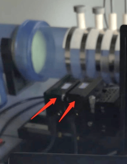
Core Sensing Equipment: Two VibroMicro VM-S-100 Laser Doppler Vibrometers.
Synchronization Trigger: An external trigger signal ensures perfectly synchronized data acquisition timebase for both devices.
Standard Impedance Tube Setup: Includes a sound source, standard test section, sample fixture, and an optical glass window for laser measurements.
Data Acquisition & Excitation: A data acquisition card, synchronized with the power amplifier and signal generator, produces sweep signals to drive the sound source and simultaneously acquires the two channels of vibration velocity data.
Software: Dedicated software for controlling the vibrometers, acquiring data, and performing post-processing and modal visualization.
Test Samples:
A. Traditional Porous Sound-Absorbing Foam
B. Membrane-type Acoustic Metamaterial (An elastic membrane stretched on a rigid frame with an added mass)
C. Lightweight Composite Panel (For UAV bulkheads)
3. Test Method & Procedure
Sample Installation: Mount the test sample at the end of the impedance tube, ensuring the laser beam can reach the sample surface through the window.
Optical Path Alignment: Precisely adjust the laser spots of the two VibroMicro devices to focus on two adjacent target points on the sample surface.
For Metamaterial B: Point A targets the center of the mass, Point B targets a blank area of the membrane.
For Composite C: Point A targets the center of the panel, Point B targets a stiffener location.
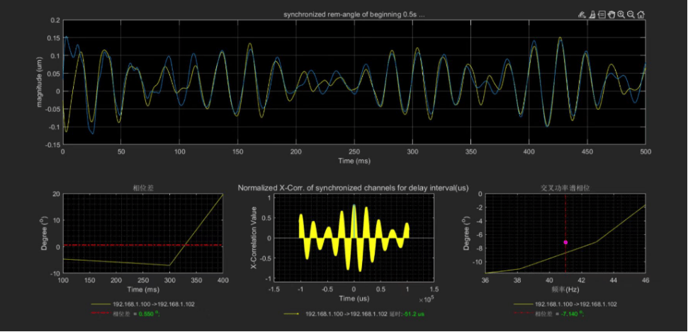
Synchronized Testing: The system emits an acoustic sweep signal (e.g., 50-5000 Hz). Triggered synchronously, the two VibroMicro devices simultaneously record the vibration velocity time-domain signals at points A and B, converting them in real-time into frequency-domain functions VA(f) and VB(f) containing amplitude and phase information.
Reference Data: Simultaneously measure the sound absorption coefficient curve of the same sample using the traditional microphone method as a performance benchmark.
4. Results & In-Depth Analysis
4.1 Case 1: Revealing the Resonance Mechanism of Membrane-type Metamaterial (B)
Traditional Method Result: The sound absorption coefficient curve shows two distinct peaks near 500Hz and 1500Hz.
Laser Vibrometry Result:
Spectral Analysis: The vibration spectrum at Point A (mass location) shows a very high resonance peak at 500Hz; Point B (membrane area) shows another peak at 1500Hz.
Phase Analysis: At 500Hz, the vibration phase of points A and B is opposite; at 1500Hz, the vibration phase is the same.
Mechanism Interpretation & Value:
This clearly demonstrates two distinct resonance modes: a "piston-like" mode of the mass at 500Hz, and a global bending mode of the membrane itself at 1500Hz.
Engineering Value: Designers now know that adjusting the low-frequency peak requires optimizing the mass and membrane tension, while adjusting the high-frequency peak requires changing the membrane's stiffness and surface density. This enables targeted design.
4.2 Case 2: Diagnosing the "Weak Point" of Lightweight Composite (C)
Problem:
Simulations predicted good sound insulation and absorption for this composite panel in the mid-frequency range, but the measured absorption coefficient was far lower than expected.
Laser Vibrometry Result:
The vibration amplitude at Point A (panel center) was very high, while it was much lower at Point B (stiffener location).
The vibration phase relationship between A and B was complex at specific frequencies, indicating the occurrence of local bending waves in the panel.
Mechanism Interpretation & Value:
The results indicated that the primary vibrational energy was concentrated in the panel areas, and the stiffeners failed to effectively suppress panel resonance. Structural vibration was the main cause of the poor acoustic performance.
Engineering Value: The optimization direction shifted from "changing the material" to improving the structural design, e.g., adding damping coatings or optimizing stiffener layout and stiffness. This avoided costly material replacement and quickly identified a solution.
5. Summary of Core Advantages
This technical solution achieves three major breakthroughs compared to traditional methods:
From "Black Box" to "White Box": Visualizes the sound absorption process, directly linking macroscopic performance with microscopic dynamic behavior.
From "What" to "Why": Not only evaluates whether material performance is good or bad but also diagnoses the underlying physical mechanisms.
From "Empirical Optimization" to "Precision Design": Provides unprecedented data support and guidance for the rapid iteration and performance optimization of new materials and structures.
6. Commercial Application Prospects
Aircraft Engine Manufacturers: Optimize the design of nacelle liners' acoustic treatments to directly reduce engine noise.
UAV Manufacturers: Apply to lightweight airframe structures and propeller design for vibration reduction and noise control, enhancing stealth and mission reliability.
Premium Automotive Manufacturers: Diagnose and optimize acoustic packages for electric vehicle powertrains and road noise, improving the driving experience.
Materials Research Institutes: Serve as a key R&D platform for developing and characterizing next-generation acoustic metamaterials and smart, tunable acoustic structures.
Conclusion:
The integration of dual-channel synchronized laser vibrometry with the impedance tube method marks a transition in acoustic material testing from mere performance evaluation to a new era of mechanism research and intelligent design. It provides a powerful and precise "key" to solving the increasingly severe noise challenges in future aerospace and other fields.