
Automated Modal Analysis with Robotic Laser Vibrometry
1. Project Background & Challenges
Modal analysis is a core method for understanding structural dynamic characteristics, validating simulation models, performing fault diagnosis, and optimizing vibration performance. However, comprehensive modal testing of complex structures faces numerous challenges:
Poor Measurement Accessibility: Areas such as structural interiors, reverse sides, or those with complex curvatures are difficult to measure directly with fixed vibrometers or scanning heads.
Low Efficiency: Manually moving sensors or repositioning laser spots for large structures (e.g., aircraft wings, car bodies) is extremely time-consuming.
Difficult Data Stitching: Integrating data from multiple local measurements into a unified global coordinate system is complex and prone to errors.
Limitations of Contact Measurements: Contact sensors introduce mass-loading effects or cannot be installed on lightweight, flexible, or hot components.
2. Solution: Robotic-Integrated Non-Contact Vibration Measurement System
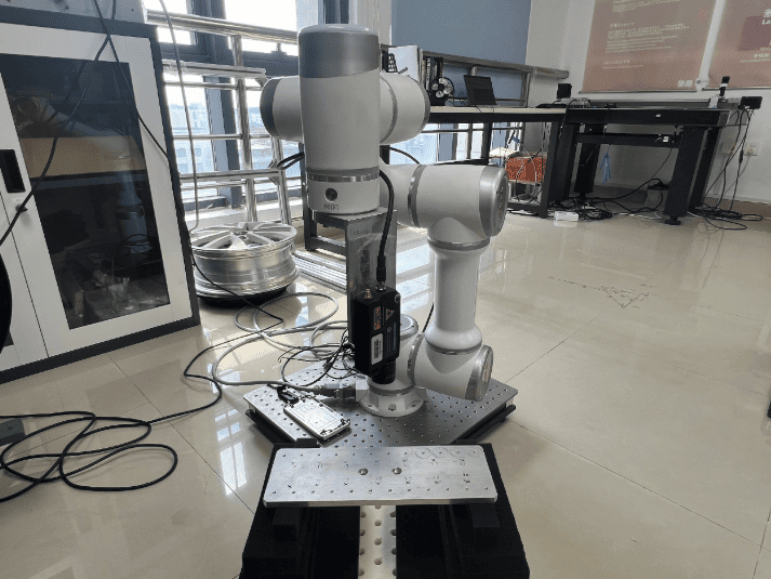
This solution integrates the Dynatronic VibroMicro VM-S-100 Laser Doppler Vibrometer as an end-effector on a six-axis industrial robot, creating a fully automated, highly flexible modal testing workstation.
System Configuration:
Core Sensing Equipment: Dynatronic VibroMicro VM-S-100 Laser Doppler Vibrometer.
Robotic Positioning System: High-precision six-axis industrial robot responsible for precisely controlling the measurement position and orientation of the laser point.
External Excitation System: Shaker, impact hammer, or acoustic exciter used to excite the structure under test.
Synchronization & Control Unit:
Robot Controller: Controls the robot's path and posture.
Synchronized Acquisition System: Synchronizes the excitation signal, robot pose data, and VibroMicro VM-S-100 measurement data.
Analysis Software: Professional modal analysis software supporting multiple-reference excitation and mode shape animation on complex geometries.
Test Objects:
A. Automotive Body-in-White
B. Helicopter Rotor Blade
C. Large Composite Panel
3. Test Method & Procedure
Digital Twin and Path Planning:
Import the CAD model of the test structure into the robot offline programming software.
Define hundreds or thousands of measurement points on the model surface.
The software automatically generates the optimal robot motion path, ensuring the laser beam remains perpendicular to the measured surface and avoids collisions.
System Calibration:
Perform hand-eye calibration to precisely establish the transformation relationship between the robot coordinate system, the laser vibrometer coordinate system, and the global coordinate system of the test structure. This is a critical step for accurate data fusion.
Automated Measurement:
The robot moves the laser vibrometer sequentially to each predefined measurement point.
At each point, the system pauses, the excitation source applies a known input (e.g., a sweep signal), and the VibroMicro VM-S-100 simultaneously acquires the Frequency Response Function (FRF) at that point.
The robot simultaneously records the precise pose of the current measurement point in the global coordinate system.
The entire process runs fully automatically without manual intervention.
Data Fusion and Analysis:
Combine the FRFs of all measurement points with their corresponding 3D coordinate information to form a global FRF matrix.
The modal analysis software processes this matrix to extract the structure's natural frequencies, damping ratios, and mode shapes.
Mode shape animations can be displayed directly on the structure's CAD model, visually showing the deformation patterns for each mode.
4. Results & In-Depth Analysis
4.1 High-Density Full-Field Mode Shapes
Result: The system can acquire data from thousands of measurement points, generating extremely smooth and precise global mode shape animations. Complex local modes (e.g., local vibration of a bracket) are also clearly captured.
Value: Provides unprecedented detailed experimental data for Finite Element Model updating, greatly enhancing simulation confidence.
4.2 Accurate Measurement of Complex Curved Surfaces
Result: The robot can flexibly adjust its posture to ensure the laser beam always has perpendicular incidence when measuring complex curves like aircraft wings or turbine blades, thus achieving the highest signal-to-noise ratio and measurement accuracy.
Value: Solves the problem of poor data quality in curved areas encountered by traditional methods.
4.3 Accessing "Hard-to-Reach" Areas
Result: The robot can plan complex paths to maneuver the laser vibrometer into narrow spaces like a car cockpit or engine bay for measurement without disassembling any components.
Value: Enables modal testing of the full structure under conditions close to the real operational state, making the results more representative.
5. Summary of Core Advantages
This solution represents a qualitative leap compared to traditional methods:
Unparalleled Flexibility: The robot's multiple degrees of freedom allow it to reach any theoretically accessible measurement point.
High Degree of Automation: Achieves full automation from path planning and data acquisition to coordinate matching, making it ideal for batch testing and quality inspection on production lines.
Perfect Data-Geometry Fusion: Each data point carries precise 3D coordinates, and mode shape visualization results are directly linked to the CAD model, facilitating engineer understanding.
Absolute Measurement Accuracy: Non-contact measurement avoids mass-loading effects, and robotic positioning ensures point repeatability, guaranteeing highly reliable data.
6. Commercial Application Prospects
Automotive Industry: Used for full-vehicle NVH performance development, automatically inspecting the modal characteristics of the body-in-white.
Aerospace: In-service inspection of large composite components like wings and fuselages.
Home Appliance Industry: Automated measurement of vibration characteristics for rotating components like washing machine drums and AC compressors.
Research Institutions: Provides a powerful experimental research platform for complex mechanical systems, bio-inspired structures, etc.
Conclusion:
The combination of the Dynatronic VibroMicro VM-S-100 Laser Doppler Vibrometer and an industrial robot represents the future direction of experimental modal analysis technology. It breaks through the bottlenecks of accessibility, efficiency, and accuracy in traditional measurements, providing industry and research with a revolutionary, fully automated dynamic testing solution capable of tackling the most complex challenges.