
Wind Turbine Blade Modal Testing Solution
Project: Wind Turbine Blade Modal Testing Solution
1. Sensor Selection & Mounting Method
Key Considerations:
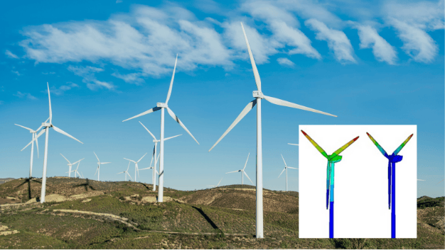
The first 6 natural frequencies (flapwise, edgewise, torsional modes) of wind turbine
blades are typically below 10 Hz, with the 1st flapwise mode as low as ~0.5 Hz.
Sensor Requirements:
Low-frequency optimized (high sensitivity at <1 Hz)
Large mass-type accelerometers (improved low-frequency response)
Directional adjustability (for flapwise/edgewise measurements)
Narrow operational bandwidth (reduces high-frequency noise interference)
Recommended Sensor:
DT1A202E Low-Frequency Piezoelectric Accelerometer
Frequency Range: 0.1–200 Hz
Sensitivity: 10 V/g
Weight: ~200 g (requires mass effect compensation)
Mounting Methods:
Thick, soft double-sided adhesive tape (damped structural foam) for minimal stiffness impact.
Magnetic base (if blade surface permits).
2. Excitation Method
Two approaches are evaluated for a 48.8m blade:
(1) Force Measurement Method (Impact Testing)
Tool: Impulse hammer with force sensor.
Advantages:
Controlled input energy.
Clear frequency response function (FRF) calculation.
Limitations:
Difficult to excite large blades uniformly.
(2) Non-Force Method (Ambient/Free-Decay Excitation)
Option A: Free-Decay Excitation
Attach a mass block (size determined by FEM static analysis) to the blade tip.
Cut the tether to trigger free vibration.
Option B: Random Excitation
Manually strike the blade at multiple points with a wooden rod.
Advantages:
No force sensor needed.
Suitable for very low-frequency modes.
3. Sensor Mass Effect Compensation
Challenge: Heavy sensors (~200 g) lower the blade’s natural frequencies.
Solution:
Use minimal sensor count (validated through iterative tests).
Apply mass correction algorithms in post-processing.
Proposed Test System
Core Equipment:
1. SE-884U Dynamic Stress-Strain Testing & Analysis System
24-bit resolution, 0.1–10 kHz sampling rate.
Supports simultaneous strain & acceleration measurement.
2. DT1A202E Low-Frequency Accelerometers
Optimized for <1 Hz measurements.
3. Dynatronic Software Suite
Real-time data acquisition.
Modal analysis (OMA/EMA modes).
Mass effect compensation tools.
4. Impact Hammer (for force method)
Adjustable tip hardness for frequency bandwidth control.
Test Workflow
1. Sensor Deployment
Install 6–12 accelerometers along the blade span (fewer points → reduced mass effect).
2. Excitation
Force method: Strike at 3–5 key points (root, mid-span, tip).
Non-force method: Use free-decay or random excitation.
3. Data Acquisition
Record time-domain responses (≥5 min for ambient vibration).
4. Modal Analysis
Extract natural frequencies, damping ratios, mode shapes.
Apply mass correction if needed.
Key Advantages
✔ Low-Frequency Precision – Reliable detection of 0.5 Hz modes.
✔ Flexible Excitation – Supports both impact and ambient methods.
✔ Minimal Mass Impact – Optimized sensor count & post-processing correction.
✔ Integrated Software – Streamlines FRF calculation & modal parameter extraction.
Applications
Blade health monitoring.
Validation of FEM models.
Aeroelastic stability studies.
This solution complies with IEC 61400-23 for wind turbine testing. Let me know if you need further customization!