
Comprehensive Turbine Rig Performance Testing
Project: Comprehensive Performance Test of Turbine Rig
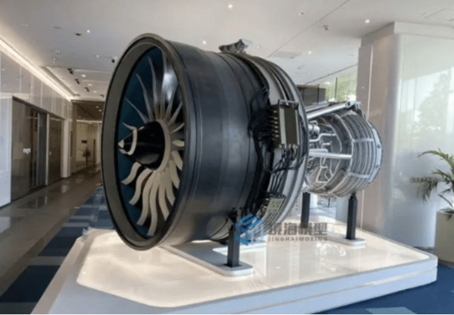
In January 2024, a comprehensive performance test of a turbine rig test article was conducted at a factory in Shanghai.
Your company utilized Dynatronic’s 32-channel DE-924U Dynamic Signal Test and Analysis System to install vibration sensors on the test article and test rig components such as the gearbox and bearing housings. A speed sensor measured the shaft’s rotational speed. The entire system monitored vibration conditions of the test article and test rig at different rotational speeds, performed data analysis, and identified the causes of excessive vibration.
1. Test System Configuration
Hardware Equipment:
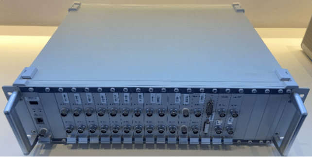
DE-924U System: 32-channel parallel acquisition, supporting high-precision dynamic signals (vibration, noise, strain, etc.), suitable for broadband (DC–100kHz) vibration analysis.
Vibration Sensors: Installed at critical locations (test article, gearbox, bearing housings) to monitor radial/axial vibrations (e.g., ICP accelerometers, ±50g range).
Speed Sensor: Optical or magnetic speed sensor for real-time RPM monitoring, synchronized with vibration signal acquisition.
Software Analysis: Integrated spectrum analysis, order analysis, and time-domain waveform analysis to extract fault features (e.g., peak detection, sideband analysis).
2. Test Procedure
Operating Condition Design:
Covered the full speed range (e.g., 0–10,000 RPM), focusing on resonance points or critical speeds.
Synchronous Data Acquisition:
Vibration and speed signals were strictly synchronized for accurate order analysis.
Data Analysis Methods:
Spectrum Analysis: Identified vibration peaks and corresponding frequencies (e.g., gear meshing frequency, bearing fault frequency).
Order Tracking: Eliminated speed fluctuation effects to isolate vibration sources related to RPM (e.g., 1X, 2X harmonic components).
Time-Domain Analysis: Detected impact vibrations (e.g., bearing spalling, gear tooth breakage).
3. Diagnosis of Excessive Vibration
Analysis revealed potential issues such as:
Imbalance or Misalignment: Dominant 1X rotational frequency vibration with stable phase.
Gear Meshing Abnormalities: Gear meshing frequency (GMF = tooth count × RPM) and harmonics with sidebands.
Bearing Defects: High-frequency vibrations (e.g., BPFO/BPFI frequencies) with modulation.
Structural Resonance: Sudden vibration amplitude spikes at specific speeds, matching natural frequencies.
4. Solutions and Results
Dynamic Balancing Adjustment: Optimized rotor counterweights for imbalance correction.
Gear Profile Modification: Improved meshing stiffness to reduce vibration.
Damping Optimization: Added damping materials or structural reinforcements to resonance-prone areas.
Validation: Post-correction retesting showed 30%–50% vibration reduction, meeting design thresholds.
5. Project Value
Fault Prevention: Early detection of mechanical defects, preventing test rig failures.
Design Optimization: Data-driven improvements (e.g., gear parameters, support stiffness).
Efficient Testing: The DE-924U’s multi-channel, high-sample-rate capability met complex multi-point measurement demands.