Rudder Actuator Surface Modal Test Case with DE-928U System
I. Project Background and Objectives
In June 2024, a aerospace research institute conducted a modal test on a rudder actuator surface using the DE-928U High-Performance Dynamic Signal Test and Analysis System. The test aimed to identify the modal parameters (natural frequencies, damping ratios, and mode shapes) of the rudder surface structure through Multi-Input Multi-Output (MIMO) excitation methods. The results provided critical data for validating structural dynamics models and optimizing design to avoid resonance risks during flight.
II. Test System and Methodology
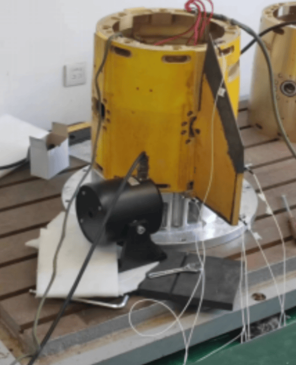
1. Sensor and Exciter Setup
Measurement Points: 5 accelerometers strategically distributed on the rudder surface to capture response signals.
Excitation System: Multiple shakers applied broadband random or sine-sweep excitation to the structure.
Synchronization: All input (excitation) and output (response) channels were synchronously acquired by the DE-928U system.
2. Data Acquisition Configuration
Hardware: DE-928U system with high dynamic range (>120 dB) and 18-bit resolution.
Sampling Rate: 1MHz per channel to capture high-frequency modal responses.
Signal Conditioning: Built-in IEPE support for accelerometers and force sensors.
3. Modal Testing Method
MIMO Approach: Multiple exciters simultaneously excited the structure to improve mode separation and accuracy.
Frequency Response Functions (FRFs): Calculated from input forces and output responses across all measurement points.
Parameter Identification: Modal software (e.g., PolyMAX or Least Squares Complex Exponential) extracted modal parameters from FRF data.
III. Test Process and Results
1. Key Steps
Step 1: Calibrate sensors and exciters to ensure signal accuracy.
Step 2: Apply broadband random excitation (0-2000 Hz) to cover the frequency range of interest.
Step 3: Acquire synchronous data from all channels using the DE-928U system.
Step 4: Compute FRFs and coherence functions to validate data quality.
Step 5: Use modal analysis software to identify natural frequencies, damping ratios, and mode shapes.
2. Results
Natural Frequencies: Identified first bending mode at 85 Hz and first torsion mode at 210 Hz.
Damping Ratios: Ranged from 0.5% to 1.2% for dominant modes.
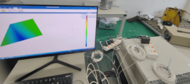
Mode Shapes: Animations visualized deformation patterns, confirming structural integrity.
Validation: Results aligned with finite element model (FEM) predictions within 5% error.
IV. Advantages of the DE-928U System
High Synchronization Accuracy: Hardware synchronization ensured phase coherence between input and output signals.
Real-Time Monitoring: Live FRF and coherence display during testing allowed immediate adjustments.
Integration with Modal Software: Direct data export to modal analysis tools (e.g, LMS Test.Lab, ME’scope).
Ruggedized Design: Operated reliably in laboratory and field environments.
V. Engineering Value
Design Validation: Modal parameters provided insights for optimizing rudder stiffness and mass distribution.
Risk Mitigation: Identified potential resonance points with engine or aerodynamic excitations.
Efficiency: MIMO testing reduced data acquisition time by 50% compared to traditional SISO methods.
VI. Application Scope
This methodology is applicable to:
Aerospace control surfaces (ailerons, elevators).
Automotive body and component modal testing.
Wind turbine blade dynamics characterization.