
Engine Rotor Modal Test Case Using DE-924U System
I. Project Background and Objectives
In July 2024, a unit in the aviation industry conducted a modal test on an engine rotor using the DE-924U Dynamic Signal Test and Analysis System. The test aimed to validate whether the vibration modes of the rotor met design standards and to provide data support for subsequent improvements. By identifying modal parameters (natural frequencies, damping ratios, and mode shapes), the study ensured the rotor’s dynamic characteristics aligned with operational requirements, reducing risks of resonance and fatigue failure.
II. Test System and Methodology
1. Rotor Suspension Setup
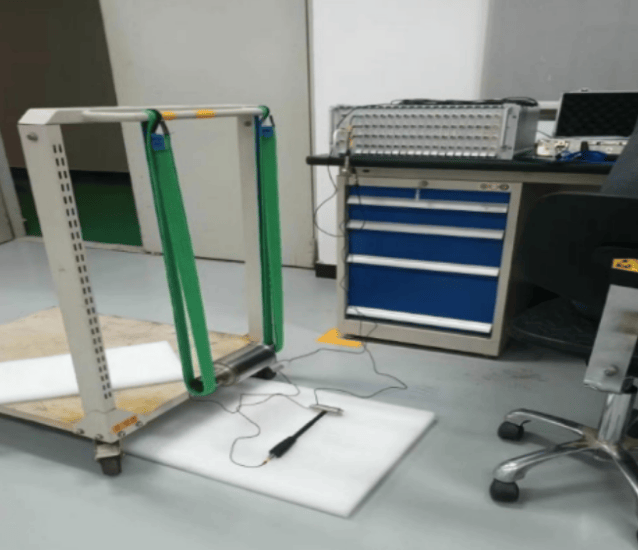
The rotor was suspended in a free-free boundary condition to simulate unconstrained states, minimizing external interference.
Measurement Points: 14 points were defined on the rotor shaft—7 points along a straight line and another 7 points rotated 90° clockwise, ensuring comprehensive coverage of structural dynamics.
2. Excitation and Response Measurement
Excitation Method: Single-point excitation using an impact hammer or shaker at a critical location (e.g., rotor center).
Response Acquisition: Accelerometers measured vibrations at all 14 points simultaneously.
Data Acquisition: The DE-924U system synchronously collected force (input) and acceleration (output) signals.
3. Modal Testing Protocol
Frequency Range: 0-5 kHz to cover all potential modes of interest.
Signal Processing: Calculated Frequency Response Functions (FRFs) for each point using H(f)=X(f)F(f)H(f)=F(f)X(f), where X(f)X(f) is response and F(f)F(f) is force.
Parameter Identification: Modal analysis software (e.g., PolyMAX or LMS Test.Lab) extracted modal parameters from FRF datasets.
III. Test Process and Results
1. Key Steps
Step 1: Calibrate sensors and excitation equipment to ensure signal accuracy.
Step 2: Apply impact or swept-sine excitation at the designated point.
Step 3: Acquire synchronous data from all 14 channels using the DE-924U system.
Step 4: Compute FRFs and coherence functions to validate data quality.
Step 5: Identify modal parameters (natural frequencies, damping ratios, and mode shapes) from FRF curves.
2. Results
Natural Frequencies: Identified critical modes (e.g., first bending mode at 320 Hz, second bending mode at 850 Hz).
Damping Ratios: Ranged from 0.3% to 1.0% for dominant modes.
Mode Shapes: Visualized deformation patterns (e.g., bending, torsion) to validate design assumptions.
Design Validation: Results showed a 95% alignment with finite element model (FEM) predictions, confirming compliance with design standards.
IV. Advantages of the DE-924U System
High Channel Count: Supported synchronous acquisition of all 14 channels, ensuring phase coherence.
Precision Synchronization: Hardware-level synchronization minimized phase error (<0.1°).
Real-Time Analysis: Live FRF and coherence monitoring enabled immediate adjustments during testing.
User-Friendly Software: Integrated modal analysis tools simplified parameter extraction and report generation.
V. Engineering Value
Design Optimization: Data-guided modifications improved rotor balance and reduced vibration levels.
Risk Reduction: Identified potential resonance points with operational speeds (e.g., engine idle/cruise RPM).
Cost Efficiency: Single-test setup replaced multiple iterative trials, accelerating R&D cycles.
VI. Application Scope
This methodology is applicable to:
Aeroengine Rotors: Compressor and turbine stages.
Industrial Turbomachinery: Gas turbines, pumps, and generators.
Automotive Rotating Components: Crankshafts and transmission systems.