

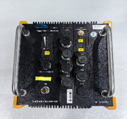
Rugged Dynamic Signal Test and Analysis System - RE-816U
The RE-816U Rugged Dynamic Signal Test and Analysis System is a high-performance solution engineered for extreme shock and blast testing environments. Featuring a 20 MHz sampling rate, 64M point cache per channel, and frequency response up to 1 MHz, it delivers precise capture of fast transient events. Its rugged design withstands harsh conditions like vibration, temperature extremes, and humidity, while offering flexible operation modes—wired, wireless, or standalone with onboard SSD storage. Ideal for aerospace, defense, automotive, and mechanical engineering, the RE-816U ensures real-time acquisition, analysis, and reliability where conventional systems can’t perform.
High-Speed Data Acquisition
64M point cache per channel for extended signal capture
20 MHz transient sampling rate for accurate high-speed recording
Frequency response up to 1 MHz for dynamic and transient measurements
Ruggedized Design for Extreme Environments
Resistant to strong vibrations, temperature extremes, and high humidity
Equipped with an industrial-grade control computer and SSD for reliability
Flexible Connectivity & Operation
Wired (LAN) and wireless (Wi-Fi) real-time data transmission
Standalone mode with onboard SSD for data storage without a PC
Data recovery and post-processing after reconnection to a computer
Real-Time Performance
Simultaneous acquisition, storage, transmission, display, and analysis of dynamic signals
| Number of Input Channel | 2 ~ 16 channels |
| Input Coupling | GND, Sin-DC, DIF-DC, AC, IEPE (ICP) |
| IEPE Power | 4mA/24V |
| Full-scale Voltage Value | ±0.02V, ±0.05V, ±0.1V, ±0.2V, ±0.5V, ±1.0V, ±2.0V, ±5.0V, ±10.0V, ±20.0V |
| Voltage Indication Error | ≤ 0.5% |
| Nonlinearity | 0.1% |
| Noise | <8μVRMS |
| CMR | ≥ 100dB |
| CMV | < ±10V (DC/AC peak value) |
| Strain Measurement | |
| Full-scale Strain Value | ±1000με, ±10000με, ±100000με |
| Indication Error | <0.5%±3με |
| Self-Balancing Range | ±10000με (±2% of strain gauge resistance) |
| Bridge Excitation | |
| Bridge Configuration | Full (Fore-Wire), Half (Fore-Wire), Quarter bridge (Three-Wire) |
| Bridge Completion Resistors | 120Ω/350Ω (Three-wire quarter bridge) 50Ω~10000Ω (Half bridge/Full bridge) |
| Bridge Voltage | 2V~24V (Within 0.05%/h) |
| Max. Output Current | 30mA |
| Accuracy | 0.1% |
| Stability | 0.05%/2h |
| LPF | |
| Filter Type | Third order Butterworth filter |
| Cut-off Frequency (-3dB±1dB) | 1kHz, 10kHz, 100kHz, PASS |
| Stop-band Attenuation | >-24dB/Oct. |
| Flatness | <0.1dB (Within 2/3 of cut-off frequency) |
| HPF | |
| Cut-off Frequency (-3dB±1dB) | 0.5Hz, 5Hz |
| Stop-band Attenuation | >-6dB/Oct. |
| Flatness | <0.1dB (Above 10 times cut-off frequency) |
| Anti-aliasing Filter | |
| Cut-off Frequency | 1/2.56 of sampling rate |
| Stop-band Attenuation | >-120dB/Oct. |
| Flatness | ±0.1dB (Within analysis frequency range) |
| Communication | |
| Interface | Gigabit Ethernet/WiFi |
| A/D Converter | 16-bit Σ-Δ |
| Freq. Response | DC~1MHz (±0.5dB ~ -3dB) (300kHz flatness) |
| Sampling Rates | |
| Continuous, All channels | 10Hz, 20Hz, 50Hz, 100Hz, 200Hz, 500Hz, 1kHz, 2kHz, 5kHz, 10kHz, 20kHz, 50kHz, 100kHz, 200kHz, 500kHz, 1MHz |
| Transient, All channels | 1kHz, 2kHz, 5kHz, 10kHz, 20kHz, 50kHz, 100kHz, 200kHz, 500kHz, 1MHz, 2MHz, 5MHz, 10MHz, 20MHz |
| Synchronization Mode | Synchronous clock box or GPS/Beidou |
| Power Supply | Lithium battery/external 220V AC / External 10~24V DC |
| Battery Life | 4h of battery life (Fully charged and simultaneous sampling of 16 channels) 8h of battery life(Option) |
| Dimensions | |
| Dimensions | 290mm×150mm×200mm |
| Weight | Approx. 8kg (16channles system with 4hrs Lithium battery ) |
| Environmental Conditions | |
| Operating Temperature | -10°C ~ 50°C |
| Operating Humidity | 5% ~ 90%RH @ 50°C |
| Storage Temperature | -40°C ~ 70°C |
| Storage Humidity | 90%RH 48h @ 60°C |
| Vibration |
Frequency Cycle Range: 5Hz ~ 55Hz ~ 5Hz Drive Amplitude (Peak): 0.19mm Sweep Frequency: ≤1Oct./min Duration of Resonant: 20min |
| Shock | 100g/(4±1)ms |
| Ingress Protection | IP65 |

Figure 1 Single System Block Diagram

Figure 2 Multiple System Block Diagram (Ethernet Synchronous Communication)

Figure 3 Multiple System Block diagram (Wifi Synchronous Communication)

DE-BPS Basic Platform Software
The DE-BPS Basic Platform Software is a powerful control and analysis solution designed for seamless integration with the RE-816U Rugged Dynamic Signal Test and Analysis System. It provides an intuitive platform for system configuration, real-time monitoring, advanced data analysis, and report generation, supporting both online and offline modes.
Key features include parameter setup, trigger controls, live waveform and FFT display, cursor-based measurements, scaling to engineering units, and long-term recording with segmented file management. It offers advanced post-processing tools such as PSD, transient analysis, and integration, along with batch processing and cross-platform export to formats like ASCII, .mat, and .csv.
With TEDS sensor auto-recognition, customizable workflows, and multi-tasking capabilities, DE-BPS ensures efficient acquisition, analysis, and reporting for complex testing scenarios.
| Accessories | |
|---|---|
|
RE-816U Main Control Module
Built-in high-performance on-chip system Gigabit Ethernet for communication with the computer Intelligent management of rechargeable lithium battery pack power supply(4h/8h) LINUX operating system Built-in electronic hard disk (expandable 128G/256G/512G/1T), Up to 16 channels for synchronous operation Operating environment meets the conditions of GB/T 6587-2012 III group. Optional GPS module, controls multiple data recorders to work wirelessly synchronously, capable of measuring the movement speed and position of moving objects. |
 |
|
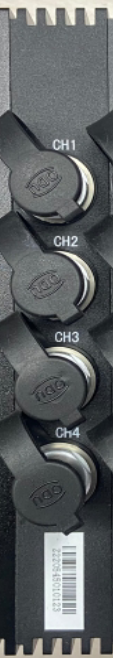
RE-816U DAQ Module(Option)
2 input channels Support GND, SIN_DC, DIF_DC, AC, IEPE input Full-scale voltage value from ±0.02V, ±0.05V, ±0.1V, ± 0.2V, ±0.5V, ±1.0V, ±2.0V, ±5.0V, ±10.0V, ±20.0V Self-Balancing Range ±20000με (±2% of strain gauge resistance) Independent 16-bit A/D converter per channel with continuous sampling rate of up to 256kHz Frequency response range from DC to 1MHz Support intelligent wire identification, TEDS sensors access and bridge self-check function Shock Resistance up to 100g/(4±1)ms IP65 |
 |
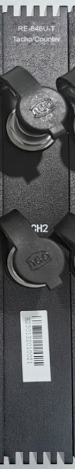
| RE-816U-T Tachometer/Counter Module(Option)
Tachometer/counter channel, through software, switches between speed measurement and counter function; Channel count: 2 channels per card; Power supply: DC 5V, 50mA; Tachometer Measurement 1) Measurement range: 30 RPM to 300,000 RPM (measured each time a revolution occurs); 2) Measurement accuracy: less than 0.05% ± 1 revolution; Counter Measurement 1) Working mode: supports forward/reverse, supports cumulative pulse counting, supports pulse counting within a unit of time; 2) Pulse count reset method: manual reset; 3) Speed timing time: can be set arbitrarily |
 |
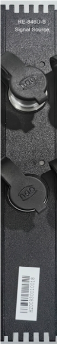
| RE-816U-S Signal Source Module(Option)
The signal source channel allows for setting the output signal parameters through software; Number of channels: 2 channels per board; Maximum output voltage: ±10Vp; Maximum output current: 5mA; Output frequency range: 0.1Hz to 20kHz; DAC resolution: 24bit; Frequency resolution: 0.01Hz; Amplitude accuracy: 1% (within the 2kHz signal range); Signal types: sine fixed frequency, sine sweep frequency, square wave, random, burst random, etc. |
 |
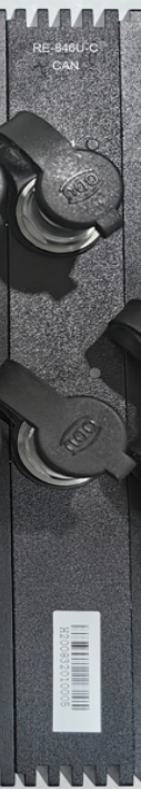
| RE-816U-C CAN Module(Option)
2 channels per module Communication protocol: Uses CAN2.0B standard communication protocol; Communication baud rate: 8000bps to 1Mbps selectable. When the data source continuously sends data, the data interval must be no less than 100ms; Communication method: Unidirectional CAN bus, capable of receiving data; |
 |
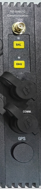
| RE-816U-C Communication Module(Option)
Wireless network antenna interface. Just tighten it clockwise during installation. Balance and sampling operations Synchronous / Line-controlled / External trigger, can be connected to a line controller or external trigger input cable. When multiple units are connected and the clock boxes are synchronized, connect to the synchronous communication interface and use the dedicated network cable of RE-816U. GPS antenna interface (optional), built-in GPS module. When installing, simply tighten the GPS antenna connector clockwise. At this time, GPS can be used for wireless synchronous acquisition between multiple instruments. |
 |
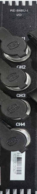
| RE-816U-I Digital I/O Module(Option)
Realize switch quantity measurement and TTL level output |
 |
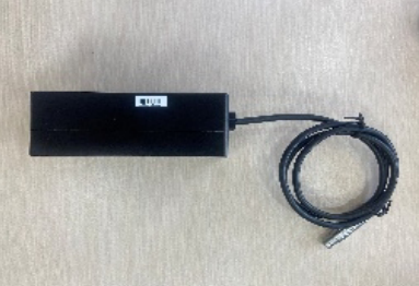
| Charger
RE-816U dedicated charger, one end is connected to the instrument for charging, and the other end is connected to 220V alternating current. |
 |
| Gigabit Network Cable
Connect the instrument to the computer for communication |
 |
| Wireless Network Connection Antenna | 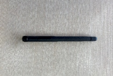 |
| C-4 Signal Input Cable
4 channel. Default 5m bare cable or 1.5 m cable with bridge box. |
 |
| DT5857-8 Charge Conditioner(Option)
Max. input charge: 105pC Input Impedance: >1011Ω Amplifier output sensitivity: 0.1mV/pC and 10mV/pC Indication error: <1% Noise: <10×10-3pC Max. bandwidth: 0.3Hz~1MHz(+0.5dB~-3dB) Distortion: <0.5%(Frequency < 30kHz) |
 |
| DT3811-8 Current Loop Conditioner(Option)
1 input channel Suitable for 2-wire or 3-wire 4~20mA sensor 24V DC power supply |
 |
| DT3814-8 Thermistor Conditioner(Option)
1 input channel. Suitable for Pt10,Pt100、Pt1000 sensors. Measuring temperature range from -200℃to 850℃. Accuracy: 0.5%±0.5℃ Iout: 1mA±2μA |
|
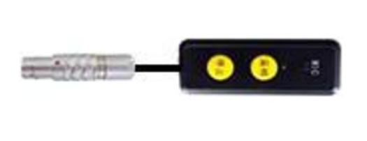
| Wireless Control/Audio Input Cable
The sampling and stopping of the line-controlled instrument, and adding sound markers to the sampling process |
 |
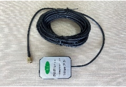
| GPS Antenna
When multiple wireless connections are in use, GPS is employed to achieve synchronous sampling among the various instrument channels. |
 |
| BNC Patch Cord
One a DB-26 connector and other is a BNC female connector, 0.1m |
 |
| BNC Cable(Option) | 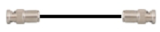 |
| IEPE Signal Input Cable(Option) |  |
| L5 Cable(Option) |  |
| Tachometer/Counter Signal Cable(Option) | 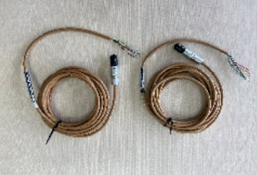 |
| Digital I/O Signal Input Cable(Option) | |
| CAN Signal Cable(Option) | 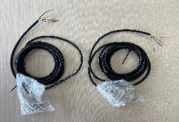 |
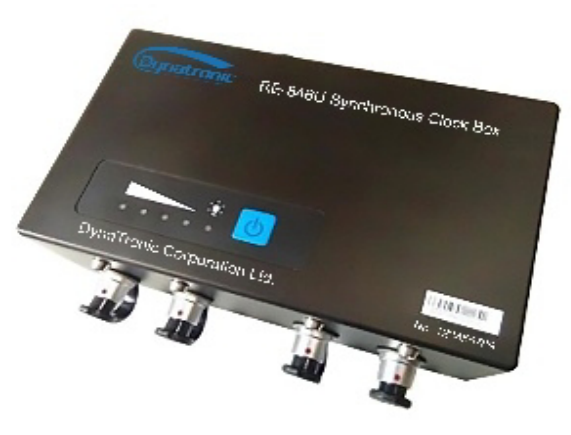
| RE-816U Synchronization Box(Option)
For use in the wired connection of multiple instruments, the channels operate in synchronization. |
 |
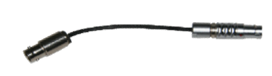
| Synchronous Clock Cable(Option) | 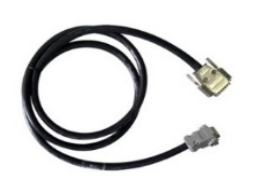 |
| Gigabit Switch(Option) | 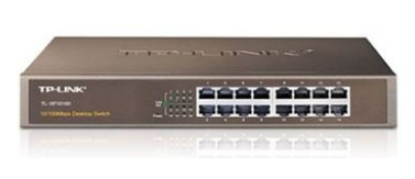 |
| Copper Core Nylon Cable Cap (with Copper Core) |  |
| Packing Case |  |
| Software CD |  |