
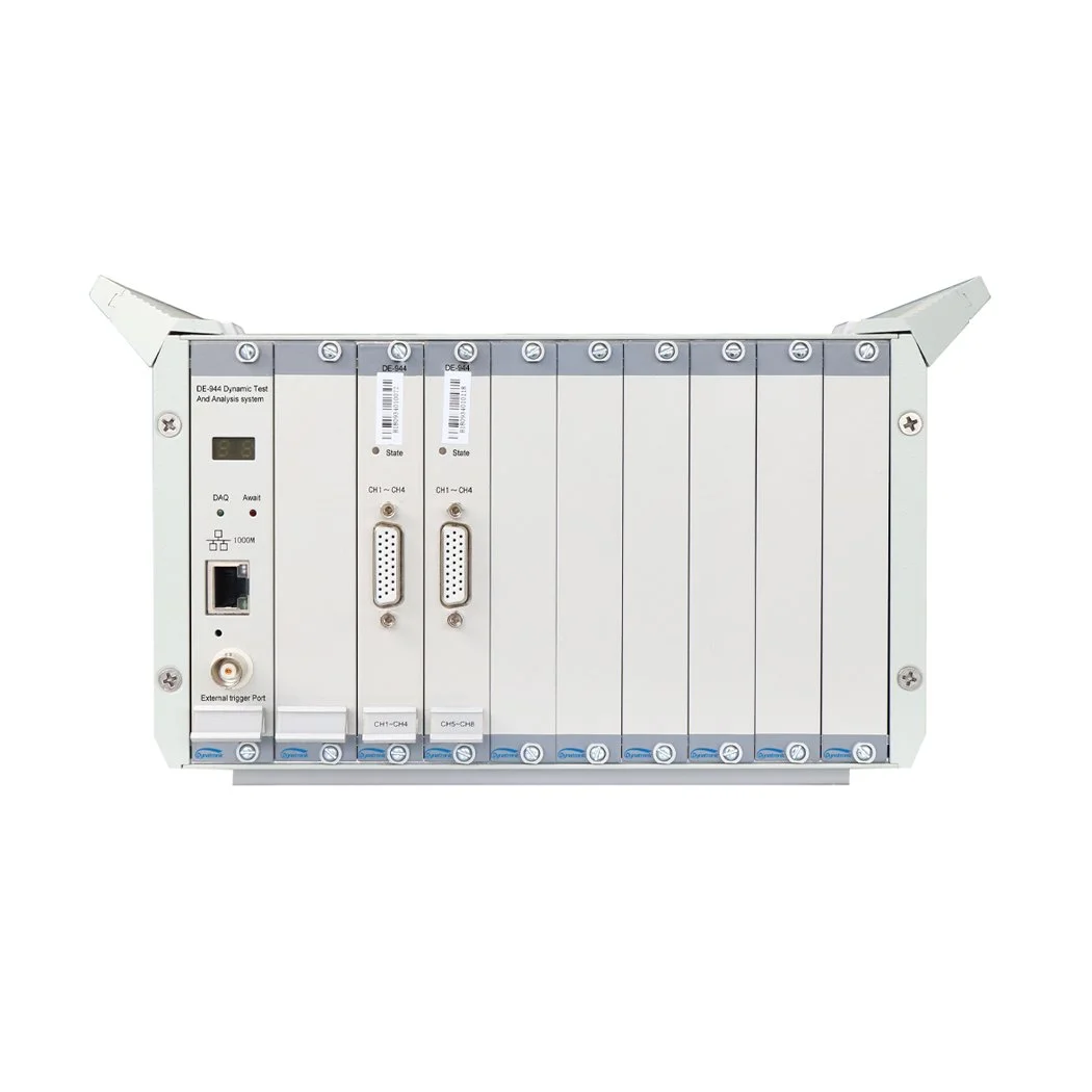
Dynamic Signal Test and Analysis System - DE-944
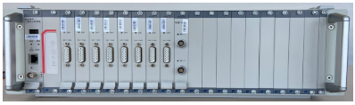
The DE-944 is a high-performance testing system specifically designed for strength and life evaluation of large-scale structures. Featuring a robust 19-inch rackmount chassis and dual-interface communication options, this system delivers exceptional testing capabilities for demanding engineering applications.
Independent 24-bit A/D converter per channel with the sampling rate of up to 256kHz
Built-in bridge completion and Excitation
Built-in 24V/4mA biasing circuit, support IEPE sensors
Built-in low-pass filter and anti-aliasing filter
Suport EID and TEDS
On-site self-checking function of stress/strain channels is supported to get the current state quickly
| Name | Detail |
|---|---|
| Number of input channels | 4 channels/card, 8/16 card slots |
| Input Coupling | GND, Sin-DC, Dif-DC, AC, Sin-IEPE, Dif-IEPE |
| Input Impedance | 10MΩ + 10MΩ |
| Input Voltage Range | ±0.1V, ±0.2V, ±0.5V, ±1.0V, ±2.0V, ±5.0V, ±10.0V |
| Indication Error | 0.2% of F.S. |
| Stability | 0.01%/24h |
| Nonlinearity | 0.1% of F.S. |
| Channel to Channel Isolation | >=80dB |
| Noise | ≦3μVRMS |
| Strain Measurement | |
| Input Strain Range | ±1000με, ±10000με, ±100000με |
| Indication Error | ≦0.5%±3με |
| Zero Drift | ≦3με/2h |
| Self-Balancing Range | ±20000με |
| Bridge Excitation | |
| Bridge Configuration | Full, half, three-wire quarter bridge |
| Bridge Completion Resistors | 120Ω / 350Ω (Three-wire quarter bridge) |
| Resistors | 50Ω ~ 10000Ω (Half bridge / Full bridge) |
| Bridge Voltage | 2V, 5V, 10V, 24V DC |
| Max. Current | 30mA |
| LPF | |
| Cut-off Frequency (-3dB±1dB) | 30Hz, 300Hz, 3kHz, PASS |
| Flatness | <0.1dB Within 1/2 of cutoff frequency |
| Stop-band Attenuation | >-18dB/Oct. |
| Communication | Gigabit Ethernet / USB 3.0 |
| A/D Converter | 24-bit A/D |
| Freq. Response |
DC~100kHz (+0.5dB ~ -3dB) 32 simultaneous inputs, up to 200kHz per channel. Over 32 simultaneous inputs, up to 128kHz per channel. |
| Anti-aliasing filter | |
| Cut-off Frequency | 1/2.56 of sampling rate |
| Stop-band Attenuation | >-120dB/Oct. |
| Flatness | ±0.05dB Within analysis frequency range |
| Power Supply | 100–240VAC / 10–30VDC, 160W (32 channels) / 320W (64 channels) |
| Dimensions | 237×133×338mm (semi 19″ chassis) 482×133×388mm (19″ chassis) |
| Weight | Approx. 7kg (semi 19″ chassis with 32 channels) Approx. 12kg (19″ chassis with 64 channels) |
| Environmental Conditions | |
| Operating Temperature | -10 to 50°C |
| Operating Humidity | 20–90%RH @40°C |
| Storage Temperature | -40 to 60°C |
| Storage Humidity | 90%RH 24h@50°C |
| Vibration Resistance |
Frequency cycle range: 5~55~5Hz Drive amplitude (peak): 0.19 mm Sweep frequency: <1 Oct./min Duration of resonant: 10min Vibration direction: x, y, z |

Figure 1 Single System Block Diagram
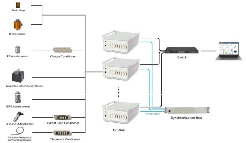
Figure 2 Multi-System Block Diagram

DE-BPS Basic Platform Software
Core Feature
Integrated Analysis Modules
Data acquisition and basic signal processing
Order analysis and field dynamic balancing
Impact waveform detection
Experimental modal analysis
Acoustic analysis
Smart Operation System
Modular management for simplified workflow
Automatic system parameter identification
Fully programmable instrument settings (range, filtering, sampling)
Virtual instrumentation with one-click configuration
Technical Specifications
Unified Platform Architecture
Supports multiple DAQ system types on single platform
Visual parameter configuration with real-time status monitoring
Data Management
Intelligent project organization for large-scale experiments
Batch processing and automated report generation
Multiple sampling modes (triggered/continuous)
Advanced Analysis Capabilities
Flexible channel grouping
Custom data flow configuration
Real-time processing (acquisition, storage, display, analysis)
Visualization Tools
Global data navigation
Multiple display modes:
Digital tables and bar charts
X-Y plotters and FFT views
Octave analysis, 2D/3D visualization
Reporting & Output
Interactive Word report generation
Multi-format export capabilities
Customization & Expansion
Open development interface
Plugin architecture for user-created modules
Shared plugin repository
Distributed System Support
Multi-client operation:
Main control terminal (full system control)
Display terminals (remote monitoring)
View layout management for field applications
Selective data storage based on bandwidth
| Accessories | |
|---|---|
|
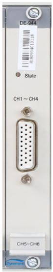
DE-944 DAQ Card
4 input channels. Support GND, Dif-DC, Sin-DC, AC, Sin-IEPE, Dif-IEPE, three-wire 1/4 bridge, 1/2 bridge, and full bridge Input. Input voltage range from ±0.1V to ±10.0V. Input strain range from ±1000με to ±100000με. Individual 24-bit A/D converter per channel with continuous sample rates of up to 256kHz. System uncertainty within 0.2% of F.S. Frequency response range from DC to 100kHz. |
 |
|
DE-92U Semi 19" 3U Chassis
CPU based on on-chip system (SOC). 8 Card Slots. Including control card, Gigabit Ethernet communication Interface. 100~240VAC/12VDC power supply. |
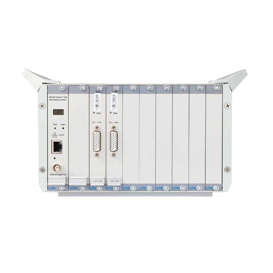 |
| DE-93U 19" 3U Chassis
CPU based on on-chip system (SOC). 16 Card Slots. Including control card, Gigabit Ethernet communication Interface, 100~240VAC/12VDC power supply. |
 |
| DT3811-8 Current Loop Conditioner(Option)
1 input channel Suitable for 2-wire or 3-wire 4~20mA sensor 24V DC power supply |
 |
| DT3814-8 Thermistor Conditioner(Option)
1 input channel. Suitable for Pt10,Pt100、Pt1000 sensors. Measuring temperature range from -200℃to 850℃. Accuracy: 0.5%±0.5℃ Iout: 1mA±2μA |
|
| DT5857-8 Charge Conditioner(Option)
Max. input charge: 105pC Input Impedance: >1011Ω Amplifier output sensitivity: 0.1mV/pC and 10mV/pC Indication error: <1% Noise: <10×10-3pC Max. bandwidth: 0.3Hz~1MHz(+0.5dB~-3dB) Distortion: <0.5%(Frequency < 30kHz) |
 |
| DT5855-8 Charge quadratic integral conditioner (Option)
Max. input charge: 105pC Amplifier output sensitivity: 0.1mV/pC and 10mV/pC Indication error: <1% Noise: <10×10-3pC Max. bandwidth: 0.3Hz~1MHz(+0.5dB~-3dB) Distortion: <0.5%(Frequency < 30kHz) Integral type: No integral, Primary integral, Quadratic integral Frequency Range: Primary integral: 10Hz~10kHz or 1Hz~1kHz Quadratic integral: 10Hz~1kHz or 1Hz~100Hz Integral Error: Primary integral: <3% Quadratic integral: <5% |
|
| DT5856-8 IEPE Quadratic Integral Conditioner (Option)
Built-in 24V/4mA biasing circuit. Amplifier bandwidth: 0.3Hz~100kHz(+0.5dB~-3dB) Distortion: <0.5%(Frequency < 30kHz) Integral type: No integral, Primary integral, Quadratic integral Integral Frequency Range: Primary integral: 10Hz~10kHz or 1Hz~1kHz Quadratic integral: 10Hz~1kHz or 1Hz~100Hz Integral Error: Primary integral: <3% Quadratic integral: <5% Dimensions: 50×35×110mm |
|
| DT5944 Signal Source Output Module (Option)
Number of Channel: 2 channels Voltage Range: ±10VP Current: Max. 5mA Frequency: 0.1~20kHz D/A Resolution: 24 bits Accuracy: 1% within 2kHz Signal Type: constant frequency sine wave, sweep frequency sine wave, square wave, random, burst random |
 |
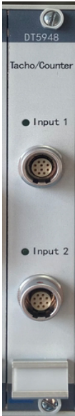
| TC-01 Tachometer/Counter Module(Option)
Number of channel:2 input channels Rotation rate measurement Range: 30 ~ 600000 rpm; Accuracy: ˂ 0.05%±1r; Input signal pulse width: >10μs PPR: 1~4096 Counter measurement Operating mode: support positive/reverse, pulse accumulative count, pulse count per unit time Reset mode: manual/atuomatic Pulse count range: 0~100k/s Power supply: 5VDC/50mA |
 |
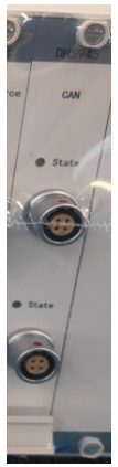
| DT5945 CAN Bus Module (Option)
Number of channel:2 channels Protocol: CAN2.0B Baud rate: 4800bps~1Mbps Communication mode: duplex CAN bus for sending and receiving Support dbc file import. Supports standard and extended frame formats. Minimum sending interval: 1s |
 |
| DT5946 RS485 Communication Module (Option)
Number of channel:2 channels Baud rate: 1200bps~115200bps |
|
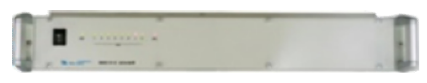
| DT5611A Synchronization Box(Option)
8 inputs. Built-in synchronization clock distributor. Support multiple clock box cascade connection. 19" 1.5U chassis. |
 |
| DT5947 Digital I/O Module (Option)
Number of channel: 8-Ch DI and 8-Ch DO Digital input: Support Dry/Wet Contact Digital output: Power Output (Ch1-Ch4) and TTL Output (Ch5-Ch8) Power Output: Max. 24V/1A |
|
| DT5987C Torsional Vibration Measurement Module (Option)
Two channels, built-in high-precision counter, can be connected to Hall sensor, magnetic sensor, encoder and other torsional vibration angular velocity measurement. |
|
| C-4 Cable
4 channel. Default 5m bare cable or 1.5 m cable with bridge box. |
 |
| Power Cable |  |
| Gigabit Network Cable
5m |
 |
| BNC Patch Cord
One a DB-26 connector and other is a BNC female connector, 0.1m |
 |
| BNC Cable(Option) | 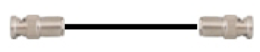 |
| IEPE Signal Input Cable(Option) |  |
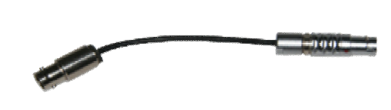
| L5 Cable(Option) |  |
| Tachometer/Counter Signal Cable(Option) | 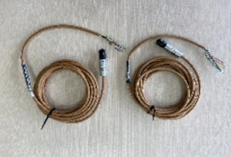 |
| Digital I/O Signal Input Cable(Option) | |
| CAN Signal Cable(Option) | 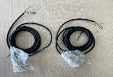 |
| Synchronous Clock Cable(Option) | 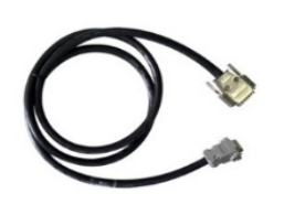 |
| Synchronous Clock Cascade Cable(Option) | 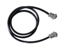 |
| Gigabit Switch(Option) | 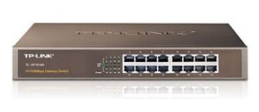 |
| Copper Core Nylon Cable Cap (with Copper Core) |  |
| Packing Case |  |
| Fuse | 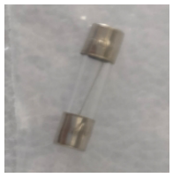 |
| Software CD |  |